Metering Knowledge, NEWS
Why DLMS Certification is Non-Negotiable for Your Smart Metering Projects in Africa | BUYI TECHNOLOGY
19
Sep
Sep
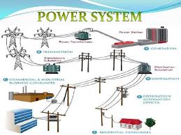
The energy landscape across Africa is transforming. With rapid urbanization, increasing demand, and a push towards greater grid efficiency, Advanced Metering Infrastructure (AMI) is no longer a luxury—it’s a necessity. Smart meters are at the heart of this revolution, acting as crucial data nodes that enable utilities to manage energy effectively, reduce losses, and empower […]